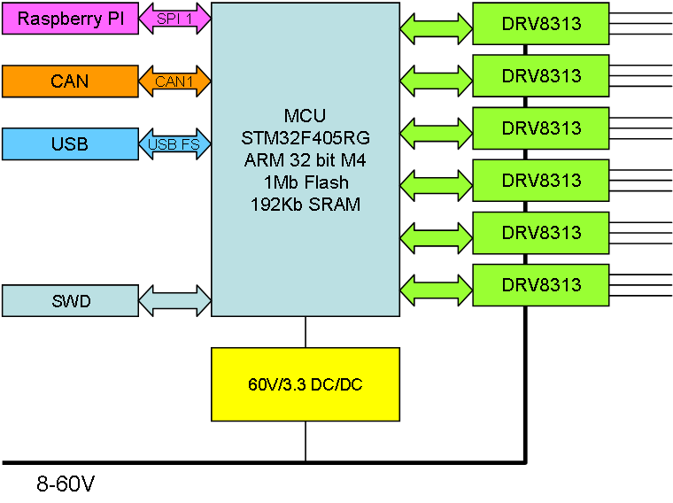
I have both 3-phase motors, stepper motors and PWM Hat on my list, so I want to use DRV8313 because this delivers 3 individual Half H-Bridges that are excellent for all of these options then combined together. I am pretty sure I can get 6 of these drivers on a Hat which would give:
- 6 x 3-Phase Motors,
- 4 x 4-wire Steppers,
- 9 x DC Motors,
- 18 x Solenoids/PWM signals.
- or any combination of these.
This would actually be a very powerfully Hat.
Looking at STM32F405RG I actually have 26 Timer pin’s with PWM capacity so this looks very doable. What I want to add in addition to DRV8313 is INA193 (or INA194) to measure current on each DRV8313. Ideally I would have this on every PWM, but I am running out of space here, so lets see where we land.
Getting 6 x DRV8313 on a Hat is very doable, but I will need a 60V DC/DC and 6 current sensors as well + a DC-Rail sensor – that is 38 extra passive Components.
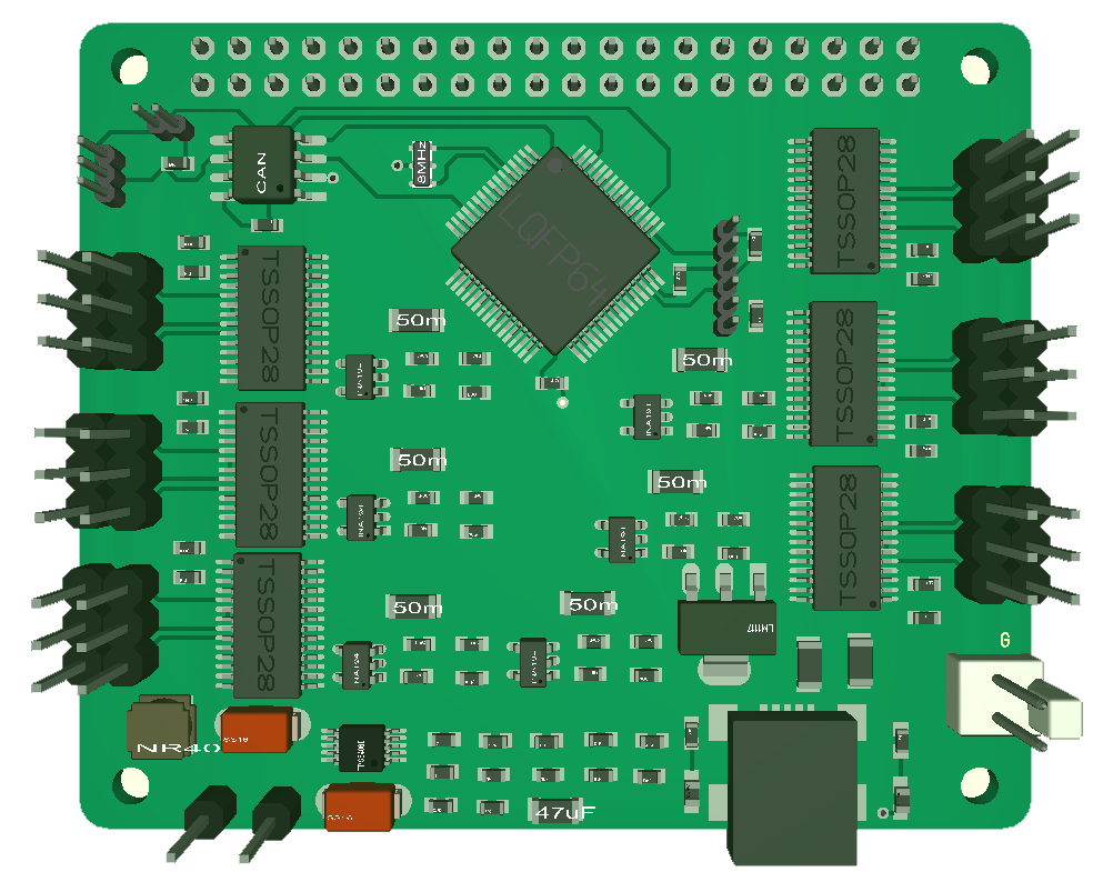
An early mock-up like the one above is just a quick exercise to place the actual components on the PCB for a reality check – and this does not look like a go to me. It is not just about placing components, but all the lanes I will need between them. And it is still capacitors etc that I would like to place here.
So what can I do?
Firstly – 60V is a bit ambiguous for this board, 36V (meaning 24V) is more workable meaning I can ditch the 60V/3.3V DC/DC. That helps a lot.
The second option is the filters that I have on the current sensors – I can remove these from electronics and do them in software – that will reduce 36 components to 12 and the density of the board is suddenly far more realistic – and less complex.
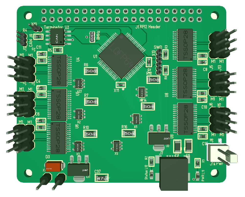
The capability to remove filters from electronics because I can do them in software is something I often face, and in this case we can due to the raw capacity of the M4 MCU. This last mock-up looks far more doable. And I am happy with a 24V limit on this board because this is for small 2-3A motors that seldom needs higher voltages. Now – lets og and design this one!


