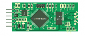

It’s only 20 by 50 mm and my most painful PCB so far. It will run a BLDC motor with up to 2-3A in peaks, 1,5A in average. As mentioned before this was a draft. I am letting this rest a bit because I was not fully satisfied with the outcome.
What is special with this one is that it supports 3 current sensors, 3 Back EMF sensors, 3 Hall sensors etc. What I am not happy with is the 1,5A limit on the DRV8313. As I routed this I felt more and more that DRV8313 ended up as a bottleneck in the middle of the PCB and was not helping on the size either because my design add so much ouside the driver chip itself.
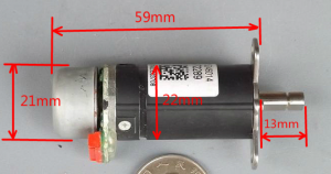
I am considering several options – one is to use SO8 size gate drivers and FET’s. This will require 6 SO8 chips, but I believe they will improve routing and the current I can get out of this solution. The small motor above will only require 0,5A, but it would be nice to have a CAN-X controlled ESC capable for larger motors. I believe we should be able to get 5-10A out.
A second option is to use DRV8301. This has the advantage that DRV8301 contain a separate Buck converter for the MCU with 1,5A available. I do however fear that this will be difficult without increasing the size of the controller.
Again – work in progress. I will be back on this and other motor controllers later.